V-MD173
6RU 17" Full Resolution Rack Mount / Standalone Monitor with Modular Inputs
Owner's Manual Spec Sheet Monitor Power Supply Chart* All pricing, features, functionality, and other product specifications are subject to change without notice or obligation.
Features:
Status Display • False Color Filter • Freeze Function • Color Temperature Presets • RGB Gain / Bias Adjust • Pixel-to-Pixel • Blue Gun • User-definable function buttons • Composite and Component loop-through • User-changeable input modules
V-ST15
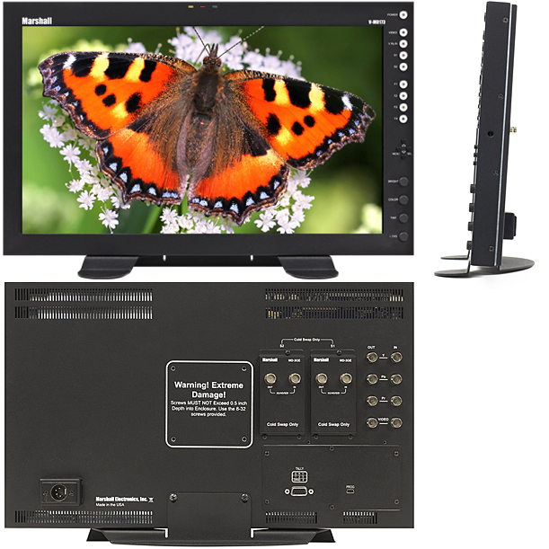
Optional Desktop StandThe V-MD173 is part of Marshall Electronics' extensive MD series of rack mount monitors. MD Series monitors offer a flexible modular solution to system integration. These rack-mountable monitors can be configured with a variety of video inputs that can be "swapped" or interchanged in the field based on your evolving needs and requirements. This eliminates the need to upgrade or replace equipment when a different input or application is required. This "future proof" solution provides flexibility and reassurance when necessary, especially in multi-monitor rack mount units.
The V-MD173 can be mounted in any standard EIA 19" equipment rack. The attached rack ears can be angled to provide the user control over the viewing angle. A VESA standard 75mm hole pattern also allows custom mounting installations. Alternately, the V-MD173 can be used in a desktop configuration with optional stand (Marshall part number V-ST15).
| Panel | Number of Panels | 1 |
| Panel Size | 17” Diagonal | |
| Resolution | 1920 x RGB x 1080 | |
| Aspect Ratio | 16:09 | |
| Active Area | 381.888 x 214.812 mm | |
| Type | LCD Panel | |
| Brightness | 400 cd/m² | |
| Contrast | 600:1 | |
| Color Gamut | YUV, RGB | |
| Viewing Angles (CR>=10) | 160° x 160° | |
| Backlight type | LED | |
| Adjustable Backlight | Yes | |
| Features | Video Formats | 1080p/1080i/720p/625i/525i |
| Loss of Input Curtain | Yes | |
| Color Temperature | D65, D55 and D93 | |
| H/V Delay | Yes | |
| Under scan | Yes | |
| IMD Functions | Yes | |
| False Color | Yes | |
| Peaking Filter | No | |
| HDMI CSC Auto | Yes | |
| HDMI Ratio Auto | Yes | |
| Pixel to Pixel | Yes | |
| Pre-set Gamma points | Yes | |
| Self-Sensing | Yes | |
| Number | 1 | |
| Modular Input Slot | 2 | |
| Re-clocked/Re-Shaped | YES | |
| Video Input Connectors | CVBS | Yes |
| YPbPr | Yes | |
| SD-SDI | Optional Module | |
| HD-SDI | Optional Module | |
| 3G-SDI | Optional Module | |
| HDMI | Optional Module | |
| DVI-I | Optional Module | |
| Optical | Optional Module | |
| Video Output Connectors | CVBS | Yes |
| YpbPr | Yes | |
| SD-SDI | Optional Module | |
| HD-SDI | Optional Module | |
| 3G-SDI | Optional Module | |
| HDMI | No | |
| Mechanical | Controls on front Panel | Yes |
| User-Defined Function Buttons | Yes | |
| RotoMenu™ Control | No | |
| Pivot Angle | Yes | |
| Handles/Rack Ears | Yes | |
| Power | Voltage | 12 VDC |
| Consumption | 3.5 AMP@ 12VDC (32W Max) | |
| Power Switch | Yes | |
| Connector | 4-Pin XLR | |
| Compliance | Compliance | CE approved |
|
Operating Temperature (C°) | 32°F to 104°F |
| Storage Temperature (C°) | -4°F to120°F | |
| Rack Unit dimensions | 17.15”W x 10.45”H x 2.00” D | |
| Weight (Main Body) | 8.75 lbs | |
| Vesa Mount Pattern | 75mm |
False Color Filter

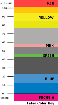
The False Color filter is used to aid in the setting of camera exposure.
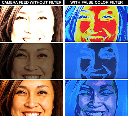
As the camera Iris is adjusted, elements of the image will change color based on the luminance or brightness values. This enables proper exposure to be achieved without the use of costly, complicated external test equipment.
To best utilize this feature, you must understand the color chart and have a basic understanding of camera exposure. Normally, when shooting subjects like people, it is common practice to set exposure of faces to the equivalent of approximately 56 IRE. The False Color filter will show this area as the color PINK on the monitor. Therefore, as you increase exposure (open the IRIS), your subject will change color as indicated on the chart: PINK, then GREY, then a few shades of YELLOW. Overexposed subjects (above 101 IRE) on the monitor will be shown as RED. In addition, underexposed subjects will show as DEEP-BLUE to DARK-BLUE, with clipped-blacks indicated with a FUCHSIA-like color. Lastly, the color GREEN is used to indicate elements of the image that are approximately 45 IRE. This represents a "neutral" or "mid-level" exposure commonly used for objects (not people).

Overexposed objects will display as RED
Underexposed objects show as
DEEP-BLUE to DARK-BLUE
Properly exposed objects will display elements of GREEN and PINK
IMD and Tally
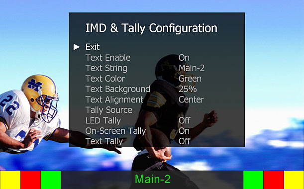
Use the "Text Enable" function to turn the MD Text feature ON. This will cause the "Text String" to appear on the lower portion of the screen. This provides the user with a 16 character on-screen text string. The color, background (opacity), and alignment of text can also be managed by the operator. This same menu allows control of Tally Source. Tally lights (both LED and on-screen) can be enabled/disabled and also set to match "Text String" color.

Optional Input Modules (Type A modules)
MD-3GE - Single 3G-SDI Input with loop-through (SDI/HD SDI compatible)MD-HDIx2-A - Two-channel HDMI Input Module
MD-DVII-A - DVI-I Input Module
MD-TC-A - One or Two Optical Inputs and/or Outputs (Specify Configuration When Ordering)
» Click here for more info on Optional Input Modules
* Input modules are optional and available at additional cost. More input modules to be offered in the future.
* Pricing does not reflect freight costs and applicable taxes and duties
* Pricing, specification and features are subject to change


